

BIM LOD and Interpreting Each Level
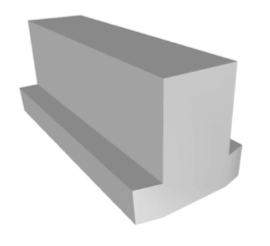
LOD 200 – Schematic Design
Schematic Designs are modeled with approximate size, shape, and location. According to the 2017 LOD Specification Guide, LOD 200 is graphically represented within the model as a generic system, object, or assembly with approximate quantities, size, shape, location, and orientation.
At this LOD, elements are generic placeholders. They may be recognizable as the components they represent, or they may be volumes for space reservation. Any information found in an LOD 200 model should be considered approximate.
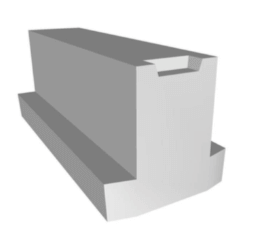
LOD 300 – Detailed Design
LOD 300 is modeled as designed-specific size, shape, spacing, and location of equipment. In other words, the quantity, size, shape, and location of the elements included in an LOD 300 model can be measured directly from said model.
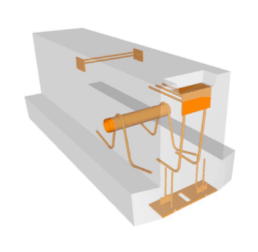
LOD 350 – Construction Documentation
LOD 350 is modeled to graphically represent a specific system, object, or assembly in terms of quantity, size, shape, location, orientation, and interfaces with other building systems. Parts that are needed for the coordination of the element with nearby or attached elements are modeled, which includes supports and connections.
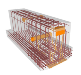
LOD 400 – Fabrication & Assembly
LOD 400 models graphically represent a specific system, object or assembly in terms of size, shape, location, quantity, and orientation with detailing, fabrication, assembly, and installation information. In addition, non-graphic information such as notes can be attached to the model as well. An LOD 400 model is modeled to highly specific detail and accuracy so that the elements in the model can be measured straight from the model itself rather than notes or dimension call-outs.
To learn more about newly adopted industry terms, you can visit: